Raspberry Pi Buster-IOT-Splash

UPDATED to openNDS! So... these Raspberry Pi0w's are quite addicting little IOT Devices (and they're really inexpensive!), but I grew tired of cobbling everything together each time. Let me introduce you to my Buster-IOT-Splash meta-release: It combines
  • Gadget Ethernet [DHCP and fixed at 169.254.3.14] so even if you mess up networking, you can plug it into your laptop and be able to fix it.
  • HostAPD to provide a dedicated WiFi network (even over the same onboard ethernet).  I use this with my MaslowCNC to have a reliable WiFi connection to my phone for controlling the router even if the upstream goes away.  Default WiFi WPA2 password: raspberry
  • openNDS- With a bit of hosts magic so it can run offline as well. This way as soon as you connect to it, the device's webpage will appear (maybe in a security browser, but...)
Warning!  Please secure this; if you install this, you have made a very open, very large access hole to your networks... luckily I have some instructions on the "openNDS" webpage that appears and SSH (default password) is enabled so you can fix them.

2020-10-07-raspios-buster-iotsplashv3.zip

This is meant for makers, so I left the size at ~4GB (50% used); you can resize it using raspi-config.  I also left a handy little script in sysprep/sysprep.sh  (sudo that from its directory) that "cleans the system for shipping" (removes ssh keys, wpa_supplicant.conf, etc).

QuickPCBs vs Normal PCBs

QuickPCB's are printed with a silver-bearing ink; for professional circuits, that means you need to keep a few things in mind:

  1. There is *no* heatsink effect. The ink conducts heat very poorly.
  2. The traces have resistance (like ohms of resistance -- see below).
    --For Logic, this will work.  For sensors/power, you need to check to see if it works--
  3. There is little/no wetting effect of solder; if you're not happy with the resistance of a trace, you'll need to fabricate a piece of wire to lay on top of the trace -- just tinning it won't do.
  4. The adhesion of the "ink" is very poor at high temperatures; if you're jumpering something or soldering a wire to the board, it's best to solder to a component lead (the larger the better; 1210 packages are good, 0805 is marginal and 0603 will just give up with any kind of tension).
  5. The "ink" is not quite flat either and it's all conductive; a 1206 package makes a good jumper for 1 trace (not two), and an 0805 package is hit or miss.
  6. Soldering is more like "leading" of a stained glass -- you have to draw your iron across it to wet an area. Remember to use a low-temp solder and a temperature-controlled iron.
  7. Also remember that the solder will try to pull the silver from the "ink" so keep the iron on for just 1-3 seconds per joint.
2016 08 25 16 36 51
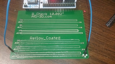
The R_Check board

I printed the R_Check board to give a real-world gauge of resistance (yes the "ink" does have specs, but toying with Ohms/mm is kind of like working with board feet of lumber); from my testing:

  • 0.010" traces have 1.13 Ohms/inch
  • 0.012" traces are about the same
  • 0.024" traces are 0.50 Ohms/inch

If you tin them:

  • 0.010 / 0.012" traces didn't change much (I got ~1.05 Ohms/inch)
  • 0.024" traces dropped to 0.39 Ohms/inch (0.30 if you re-tin by hand)

I did the tinning as part of the paste-solder-reflow (I can put parts on the board and send you completed boards, but that's going to cost more than $20 -- and the solder paste has a "stencil time" of 2 hours, so shipping a pasted board won't work very well). I then re-tinned with an iron to "spread the solder by hand."

2016 08 25 16 36 59
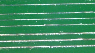
Close-Up of the tinned traces


QuickPCB’s are live!

If you've wanted a quick-turn PCB (not willing to wait 2 weeks for OSHPark), and are willing to live with some limitations:

  • No thru-holes, SMT only, only copper layer (no soldermask or silkscreen)
  • Single-Sided, 4" x 5" boards (or 3" x 4" boards)
  • Traces are conductive ink (works well, but I wouldn't do high currents without tinning or adding a wire)
  • Larger sizes & spacing than a copper PCB: 
    • Minimum trace width: 0.2mm / 8 mil
    • Minimum passive size: 1608 [metric] / 0603 [English]
    • Minimum spacing: 0.8mm / 30 mil
  • Need to use a temperature controlled iron (ideally, use Sn62 alloy @ 215c / 420F)

I can get you PCB's in 2-3 days (you send the file and PayPal the money, I drop the boards in USPS post as soon as they're done) -- faster if you're in the Atlanta area, especially if you get me the files before noon!

$20/1, $30/2 and $40/3

Send your inquiry to , and I'll get it shipped to you quickly.

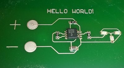
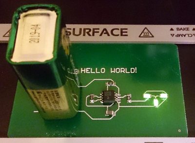
Initial Hello World PCB (a 555 timer blinking some LEDs):
 

2016 08 12 23 56 36

2016 08 13 00 07 38
 

Crap! Site was hacked in the worst way!

I fixed it... but for a while (at least 6/13/2016 21:00 EDT - 6/14/2016 09:00 EDT) my site was dropping crypto malware. PLEASE SCAN YOUR SYSTEMS. The hack may have been as early as 5/18/2016.

I use CryptoPrevent on all systems that I touch. Another tool that I'm finding very handy is the GWX Control Panel as it seems to be the best way to thwart Microsoft's insistent Windows 10 Update.

Ruffles for 3D Printing…

 Just a note I saw... interesting concept if you have a solid 0-backlash Z mechanism:  make the hotend travel in waves so now your "molten layer" isn't a single height all the way around.  Should make for a much stronger print!
http://makertum.com/en/interlocking-non-planar-layer-fdm/

CobbleBot dual extruder test

Works, but needs more work.

image

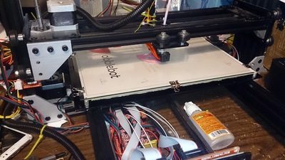
CobbleBot Vanguard XL is Alive!

I've been impressed with Robo3D.  They've sent me replacement parts, and my "out-of-the-box" experience required only minor tweaks, so I went for the "Kit Option" for my 2nd printer.

My CobbleBot Vanguard, IMHO, is unfinished.  There were no/missing instructions for:

  1. Putting the guide wheels together (you needed to add some spacers or the bearings wouldn't function properly)
  2. Breaking in the Z Ballscrew
  3. Aligning the Z Axis so it doesn't bind
  4. Routing the wires (and with 2 extruders, neatness counts...)
  5. Mounting the extruders (the supplied Teflon tubing wouldn't let me put them in the "obvious spot").
  6. Proper home-switch mounting
  7. Mounting the heated bed (thank you Mac Quillian)
  8. Calibrating the stepper motor drivers

And so far, operation has been challenging:

  1. Adjusting the Z0 height (Robo3D had an adjustment screw; now it has autolevel)
  2. Since only one side is driven in Z, there is considerable droop across the X axis.
  3. CobbleBot seriously underestimated the required power supply.  10A may be fine without a heated bed, but with the heated bed, you need >16A (the bed draws a little over 10A on its own!).  I'm now using an ATX power supply with 24A capacity.

But... it is Alive. Now to dial it in....

2016 04 13 21 40 59
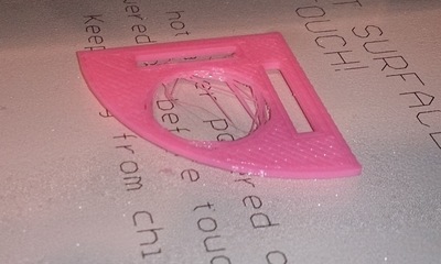
The Nickel Calibration Piece
2016 04 13 21 38 11
2016 04 13 21 38 11

Drawer Slide-Nylon

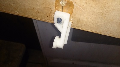
I couldn't find the slider-idler bracket for my kitchen drawer at Home Depot, so I printed one.

2016 04 03 13 14 26
http://www.thingiverse.com/thing:1461630

No, it doesn't roll, but the drawer still works well.  I printed it in Nylon so it's dang near indestructible.

Robo3D [KS] Glass Plate

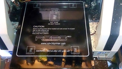
 A lot of people are worried about contaminating the bearings and bushings if they use hairspray; I decided to use a removable plate of glass to not worry about the issue:

2016 04 02 15 13 51
Glass plate held in with binder clips.  Sorry about the filament bits!
  1. Go to Lowes (since Home Depot won't cut glass) and get a 10x12" piece of glass.  Have them trim it to 10x10 (unless you want to drill holes in it for the bed bolts to go through it.  Better yet, get 2 or 3 so you can have 1 "ready" for easy swapping.
  2. Cut a notch in the front-left leg so you can have the full range of motion without hitting a micro-binder-clip
  3. Apply hairspray/abs juice/etc to the plate of glass while it is not in your printer.  Wait for it to dry.
  4. Secure it to your printer with 3 binder clips.  Be sure it's flat on the bed with nothing between the bed and the glass.
  5. Adjust Z height if you don't have autolevel.

Now you can print with hairspray without worrying about it contaminating your bearings!

3D Printed Magnets

Or at least 2D printed ones: https://www.youtube.com/watch?v=IANBoybVApQ
Go to 5:40 to start seeing demonstrations -- a magnetic spring (where attraction and repulsion cancel each other out to make a stable point), and a catch that latches when you rotate!

Nifty stuff!