Tag Archives: thormj

QuickPCBs vs Normal PCBs

QuickPCB's are printed with a silver-bearing ink; for professional circuits, that means you need to keep a few things in mind:

  1. There is *no* heatsink effect. The ink conducts heat very poorly.
  2. The traces have resistance (like ohms of resistance -- see below).
    --For Logic, this will work.  For sensors/power, you need to check to see if it works--
  3. There is little/no wetting effect of solder; if you're not happy with the resistance of a trace, you'll need to fabricate a piece of wire to lay on top of the trace -- just tinning it won't do.
  4. The adhesion of the "ink" is very poor at high temperatures; if you're jumpering something or soldering a wire to the board, it's best to solder to a component lead (the larger the better; 1210 packages are good, 0805 is marginal and 0603 will just give up with any kind of tension).
  5. The "ink" is not quite flat either and it's all conductive; a 1206 package makes a good jumper for 1 trace (not two), and an 0805 package is hit or miss.
  6. Soldering is more like "leading" of a stained glass -- you have to draw your iron across it to wet an area. Remember to use a low-temp solder and a temperature-controlled iron.
  7. Also remember that the solder will try to pull the silver from the "ink" so keep the iron on for just 1-3 seconds per joint.
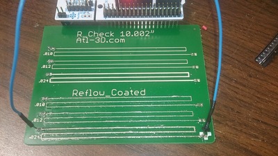
2016 08 25 16 36 51
The R_Check board

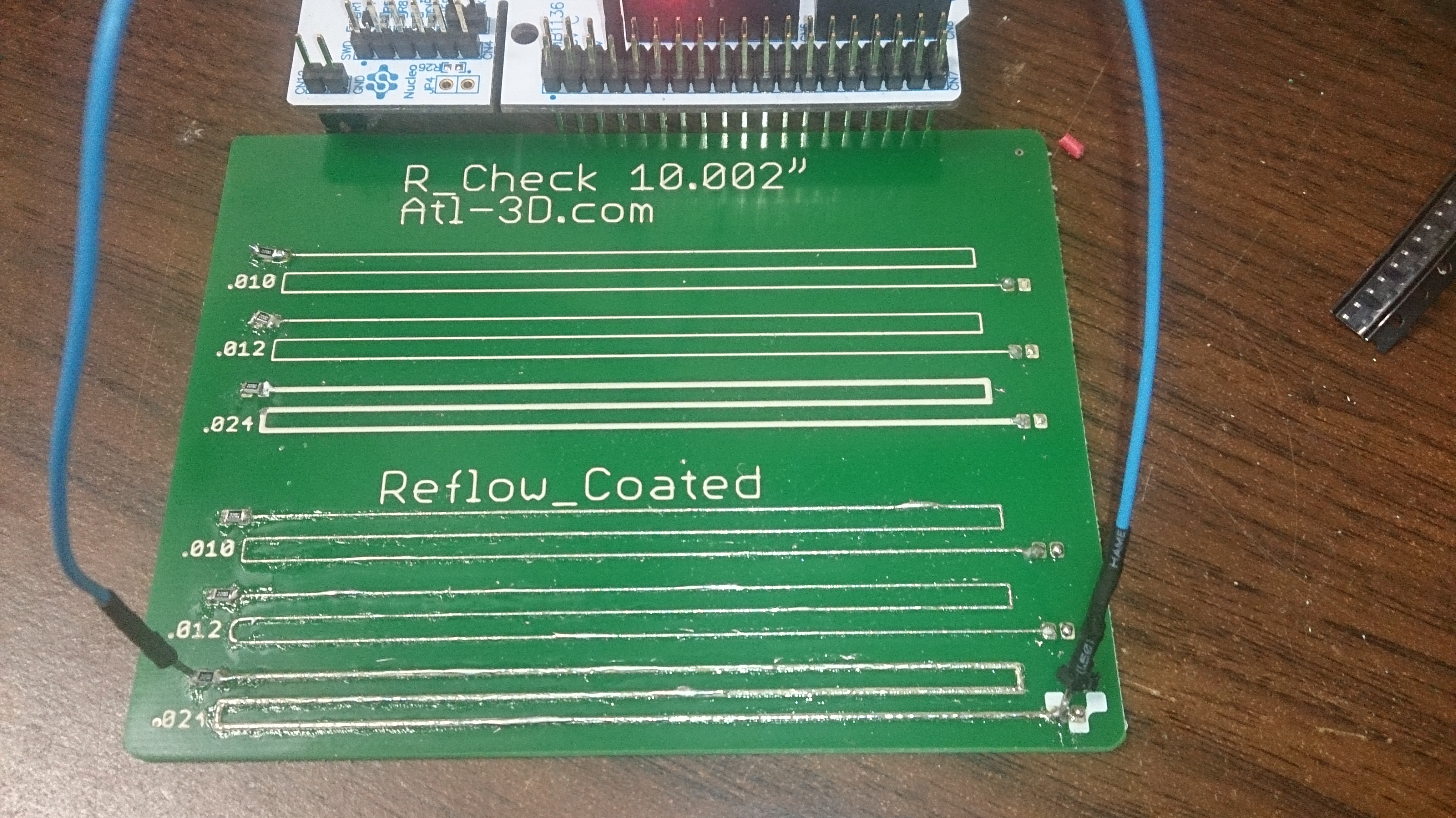
I printed the R_Check board to give a real-world gauge of resistance (yes the "ink" does have specs, but toying with Ohms/mm is kind of like working with board feet of lumber); from my testing:

  • 0.010" traces have 1.13 Ohms/inch
  • 0.012" traces are about the same
  • 0.024" traces are 0.50 Ohms/inch
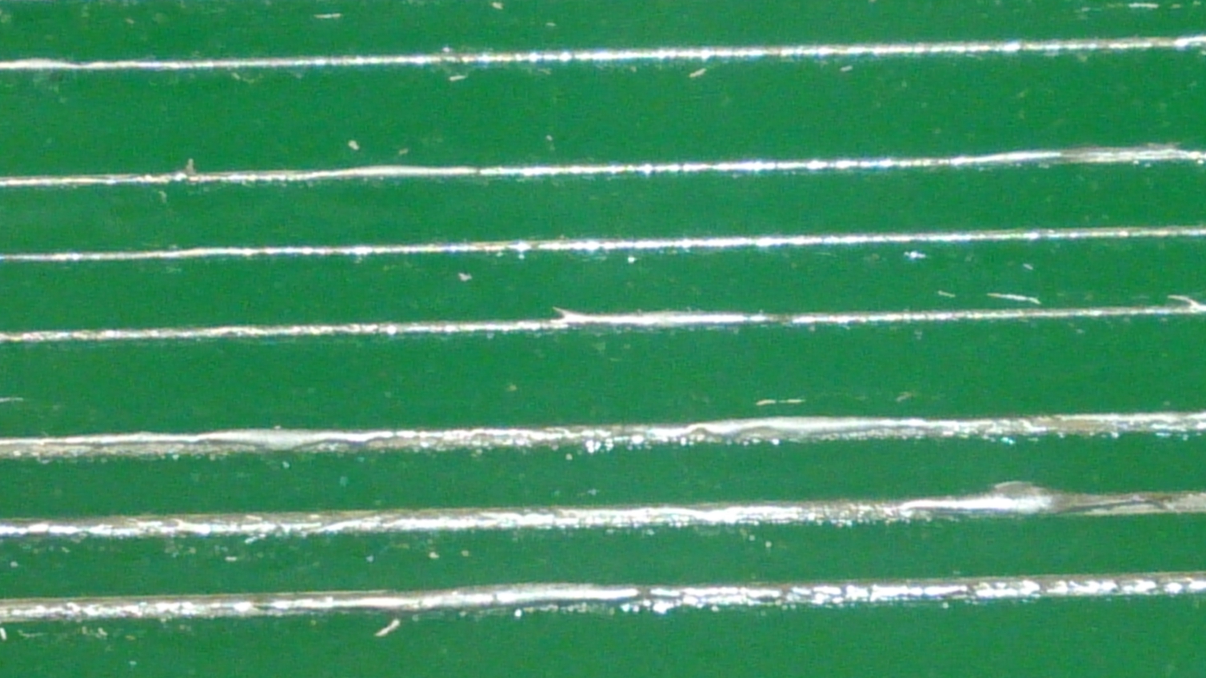
If you tin them:

  • 0.010 / 0.012" traces didn't change much (I got ~1.05 Ohms/inch)
  • 0.024" traces dropped to 0.39 Ohms/inch (0.30 if you re-tin by hand)

I did the tinning as part of the paste-solder-reflow (I can put parts on the board and send you completed boards, but that's going to cost more than $20 -- and the solder paste has a "stencil time" of 2 hours, so shipping a pasted board won't work very well). I then re-tinned with an iron to "spread the solder by hand."

2016 08 25 16 36 59
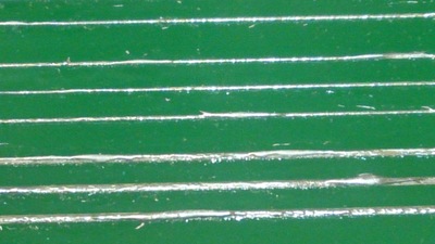
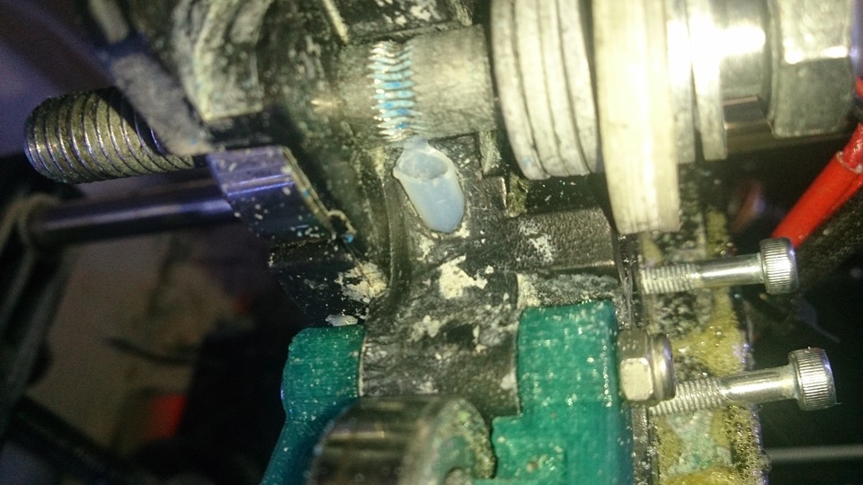
Close-Up of the tinned traces


QuickPCB’s are live!

If you've wanted a quick-turn PCB (not willing to wait 2 weeks for OSHPark), and are willing to live with some limitations:

  • No thru-holes, SMT only, only copper layer (no soldermask or silkscreen)
  • Single-Sided, 4" x 5" boards (or 3" x 4" boards)
  • Traces are conductive ink (works well, but I wouldn't do high currents without tinning or adding a wire)
  • Larger sizes & spacing than a copper PCB: 
    • Minimum trace width: 0.2mm / 8 mil
    • Minimum passive size: 1608 [metric] / 0603 [English]
    • Minimum spacing: 0.8mm / 30 mil
  • Need to use a temperature controlled iron (ideally, use Sn62 alloy @ 215c / 420F)

I can get you PCB's in 2-3 days (you send the file and PayPal the money, I drop the boards in USPS post as soon as they're done) -- faster if you're in the Atlanta area, especially if you get me the files before noon!

$20/1, $30/2 and $40/3

Send your inquiry to , and I'll get it shipped to you quickly.

Initial Hello World PCB (a 555 timer blinking some LEDs):
 

2016 08 12 23 56 36

2016 08 13 00 07 38
 

CobbleBot Vanguard XL is Alive!

I've been impressed with Robo3D.  They've sent me replacement parts, and my "out-of-the-box" experience required only minor tweaks, so I went for the "Kit Option" for my 2nd printer.

My CobbleBot Vanguard, IMHO, is unfinished.  There were no/missing instructions for:

  1. Putting the guide wheels together (you needed to add some spacers or the bearings wouldn't function properly)
  2. Breaking in the Z Ballscrew
  3. Aligning the Z Axis so it doesn't bind
  4. Routing the wires (and with 2 extruders, neatness counts...)
  5. Mounting the extruders (the supplied Teflon tubing wouldn't let me put them in the "obvious spot").
  6. Proper home-switch mounting
  7. Mounting the heated bed (thank you Mac Quillian)
  8. Calibrating the stepper motor drivers

And so far, operation has been challenging:

  1. Adjusting the Z0 height (Robo3D had an adjustment screw; now it has autolevel)
  2. Since only one side is driven in Z, there is considerable droop across the X axis.
  3. CobbleBot seriously underestimated the required power supply.  10A may be fine without a heated bed, but with the heated bed, you need >16A (the bed draws a little over 10A on its own!).  I'm now using an ATX power supply with 24A capacity.

But... it is Alive. Now to dial it in....

2016 04 13 21 40 59
The Nickel Calibration Piece
2016 04 13 21 38 11
2016 04 13 21 38 11

Drawer Slide-Nylon

I couldn't find the slider-idler bracket for my kitchen drawer at Home Depot, so I printed one.

2016 04 03 13 14 26
http://www.thingiverse.com/thing:1461630

No, it doesn't roll, but the drawer still works well.  I printed it in Nylon so it's dang near indestructible.

Robo3D [KS] Glass Plate

 A lot of people are worried about contaminating the bearings and bushings if they use hairspray; I decided to use a removable plate of glass to not worry about the issue:

2016 04 02 15 13 51
Glass plate held in with binder clips.  Sorry about the filament bits!
  1. Go to Lowes (since Home Depot won't cut glass) and get a 10x12" piece of glass.  Have them trim it to 10x10 (unless you want to drill holes in it for the bed bolts to go through it.  Better yet, get 2 or 3 so you can have 1 "ready" for easy swapping.
  2. Cut a notch in the front-left leg so you can have the full range of motion without hitting a micro-binder-clip
  3. Apply hairspray/abs juice/etc to the plate of glass while it is not in your printer.  Wait for it to dry.
  4. Secure it to your printer with 3 binder clips.  Be sure it's flat on the bed with nothing between the bed and the glass.
  5. Adjust Z height if you don't have autolevel.

Now you can print with hairspray without worrying about it contaminating your bearings!

3D Printed Magnets

Or at least 2D printed ones: https://www.youtube.com/watch?v=IANBoybVApQ
Go to 5:40 to start seeing demonstrations -- a magnetic spring (where attraction and repulsion cancel each other out to make a stable point), and a catch that latches when you rotate!

Nifty stuff!

Replace Extruder Bolts

Let's face it, Phillips-head bolts tend to cam-out and destroy themselves.  Put them on a moving platform and you have a recipe for disaster.  Replace the 2 bolts with socket-head-cap-screws (Allen-head bolts), and you'll be much happier!

1/8 Birch Ply – Awesome. Paint – Good. Anodize, not so much.

I can cleanly cut/engrave 1/8" thick birch ply.

2016 03 25 19 00 54
2016 03 25 19 00 54

And I can burn acrylic paint off aluminum in a very nice way:

2016 03 28 09 36 29
2016 03 28 09 36 29

But hard brown anodizing is so faint that it's hard to see and disappears if you put water on the piece.

2016 03 27 17 59 21
2016 03 27 17 59 21

Extruder Dry Lube

Something that helps a great deal is making the Filament Path have as little friction as possible.  You can't use Teflon for the purpose because it decomposes at high temperatures, but you can use 2 other lubricants:

Tungsten Disulfide (WS2) - http://amzn.to/1UBiGog
Hexagonal Boron Nitride (HBN) - http://amzn.to/1ROpa2n

I generally uses the the WS2 spray because it's much cheaper and I didn't see any larger benefits with the HBN spray...

Both of these mechanically-bonded powders; they have to be "wrung into place"; to do that, I use the following process:

  1. Do a Nylon-Cold-Pull and repeat as necessary to clean/clear the nozzle.
  2. Open the idler pulley so you can insert the spray tube directly into the filament path
  3. Cut a bit of filament so that you can bottom it out and still have it be long enough to put into a drill chuck.  Nylon preferred; if PLA, make sure the hotend is cold before continuing.
  4. Using the spray tube, squirt some lubricant into the filament path.  Protect the print bed from overspray!
  5. Insert the cut filament into the hole and bottom it out.  Chuck it in a drill and twirl it for 5 seconds
  6. Repeat 4&5 3-5 times.
  7. Now do a Nylon-Cold-Pull.  You'll find that it is much easier to pull the Nylon out.

I also use the spray to lubricate:

  • Hobbed bolt - makes it easier to clean
  • Extruder bearings - makes it easier to move even if the gear is on tight
  • Y-Axis idler pulley
  • Z-Axis screws

I've found that normal chain lube is better for the rods & rails, and YMMV on the idler & screws, but if you lube the hobbed bolt, as counterintuitive as it sounds, it doesn't affect the extrusion force and it makes it much easier to clean out after a jam (use a wire brush instead of picking each slot one-by-one with a razor blade).

PTFE support for Robo3D

With the stock Robo3D, there is a large gap between the hobbed bolt and the bottom; this causes some issue with normal ABS (PLA is usually stiff enough) and makes Flex almost impossible to use (maybe usable at 1/4 speed, but if you see a z-kink when you're done, you know you've gone too fast).  

Some people suggest using a ferrule from a mechanical pencil to cover the gap, but I think I did one better -- I put a PTFE tube from the hobbed bolt all the way down to the top of the hotend (for those with an E3Dv6, I'd recommend removing the PTFE tube from it and making a single extension all the way down:

2016 03 29 23 01 58
PTFE Support Tube, bearing removed for clarity.  I need to clean the bolt again...
  1. Remove hotend, release the idler pulley, and remove the hobbed bolt - this should leave nice access to the filament path.
  2. Remove any fittings from the top of the hotend, and if you can feed the new PTFE tube into the hotend (eg, E3Dv6, but not the original Robo3D), remove the PTFE tube from the hotend; measure this and add 3" to that -- this is the starting length of the your new PTFE tube.
  3. Cut a new piece of PTFE tubing to the length necessary to go from the hobbed bolt until it bottoms out in the hotend.  Too long doesn't matter.
  4. Sharpen one end of the PTFE tubing with a manual pencil sharpener, just to put a bevel on it (I should work out a better way of aligning this, but this works very well).
  5. Bore out the plastic-path with a 5/32 drill bit (this part was easy for me because I had a right-angle drill) -- Don't hit the print bed.
  6. Blow out the dust.
  7. Feed a length of PLA through (in order)
    1. PTFE tubing
    2. Filament Path of extruder
    3. Hotend (hotend should be cold... this is just for alignment purposes.
  8. Push the PTFE tubing down through the Filament Path until it comes clearly out the bottom and you can put it into the hotend; bottom it out in the hotend (this is a bit hard-- I made it a tight fit so I didn't have to worry about the PTFE tube migrating up into the hobbed bolt on retracts).
  9. Push the hotend (with PTFE and filament) back into position - this should make a length stick out where the hobbed bolt goes.
  10. Secure the hotend in place; the PTFE tubing should still be bottomed out in it.
  11. Pull PLA out, and trim the PTFE tube so you can put the hobbed bolt in.
  12. Close the mechanism gently, and continue trimming the PTFE tube with a razor blade until the idler doesn't squish the PTFE tube -- make the cut match the angle of the idler if possible.  Don't let the scrap fall into the tube.
  13. You probably don't have to, but you can remove the hobbed bolt, and bore the PTFE tube with a countersink bit just a bit to make a funnel shape to make it easier to load the filament; if you do this, you have to disassemble and then do steps 6-10 again to make sure you don't get PTFE dust in your hotend (that will cause clogs).

With this, there's almost no dead-space between the feed rollers of the extruder and the PTFE support tube, so even flex won't kink up in it.  You might have to cut the filament at a 45 angle if you didn't use a pencil sharpener in step 4.

After you do this, you might want to use a PLA "guide" whenever you remove and reinstall the hotend to make sure it stays aligned when reinstalling the hotend (or you have to use a 45 degree filament cut).

Should I make an Instructable out of this?  Then the pictures would be a little more meaningful...

-Thor